[Upcoming] Micro Seiki MB-14 Turntable Autoreturn Lever
Table of Contents
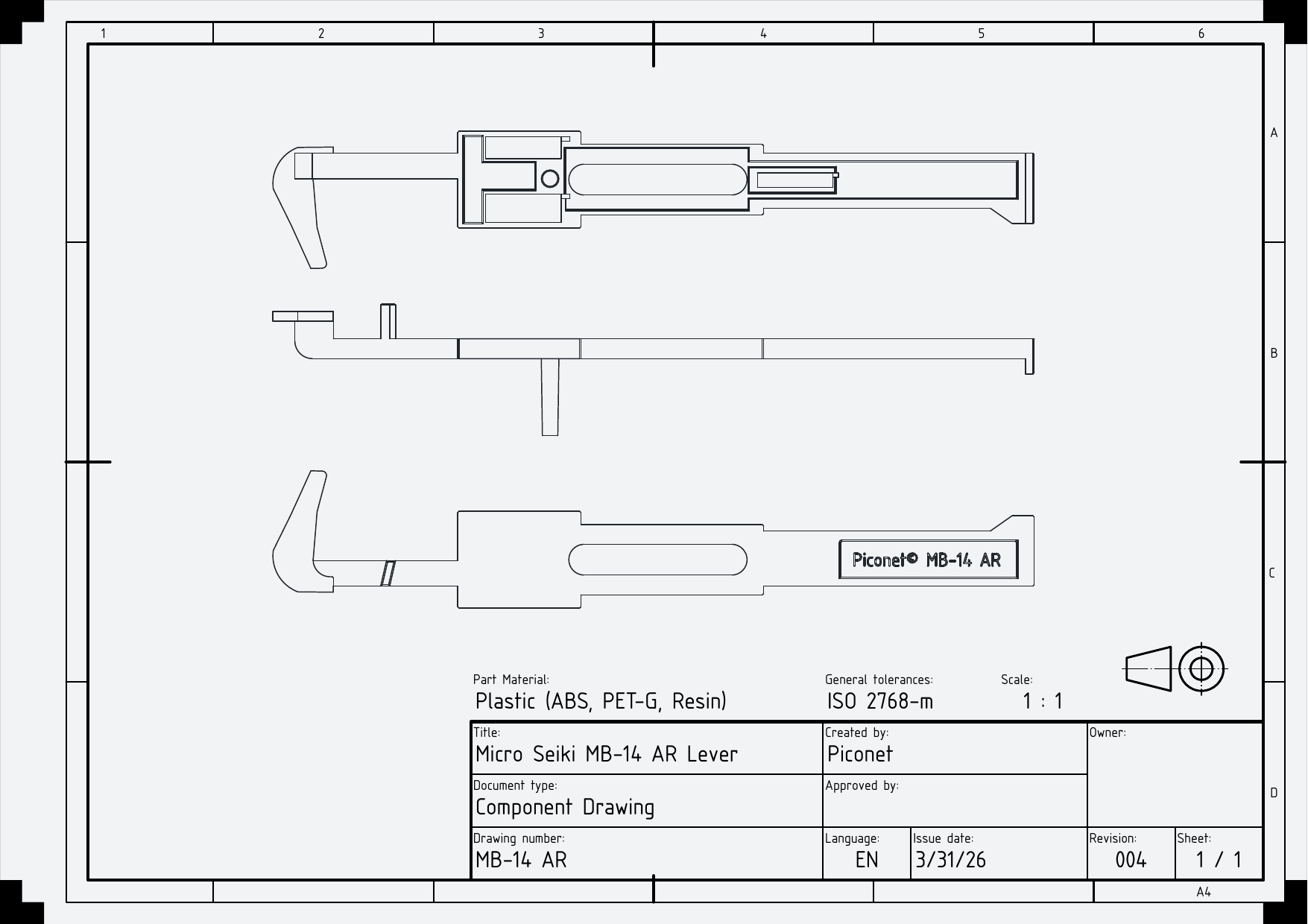
A replacement auto-return lever for a Micro-Seiki MB-14 Turntable. A commonly problematic part, owing to the small tab that interfaces with the cam for the auto-return mechanism
MB-14's with a broken auto-return bracket will continuously raise and lower tonearm as the platter rotates (as the lack of the small tab renders the mechanism unable to exit this path around the cam).
The part is designed for printing on an SLA printer, or a printer of greater detail. However printing on a typical FDM printer will likely also be possible.
1. Technical Drawing
2. Photographs
[top-side] [bottom-side]
3. Printing Instructions
3.1. SLA Printing
I would suggest using an opaque ABS-like resin, such as made by SUNLU, with supports. Followed by washing in 99.9% isopropyl alcohol, and curing for a length of time appropriate to your resin.
Atypical resins such as water-washable or 'eco/green' should be fine with this print, as the model provides additional structural support to the 'claw' that engages with the cam. However these resins tend to be more brittle, so your mileage may vary.
Further printing parameters, such as orientation, may depend on your printer. With that said, parts in contact with the cam require a smooth finished surface, and drainage channels (to avoid suction cups) have been placed in the corner of the ball-bearing slots. You should use this to inform your orientation.
Ensure the part is fully cured before taking it anywhere near your turntable. The ball-bearings benefit from a solid, normal surface to allow the lever to glide, and resin that is not fully cured will retard this movement (and potentially harm you or your turntable through toxic exposure to fumes).
3.2. Fused Deposition Modeling (FDM)
Similar instructions apply to FDM prints as with SLA prints.
It is recommended to print at the highest quality you can, with significant infill.
While printing in any material is possible, care should be taken while selecting your filament to ensure minimal warping. As the lever is intended to move unimpeded in normal operation, it is unlikely for the lever to warp when in use. Due diligence is nonetheless recommended.
4. Installation
The main components of the MB-14 can be accessed by removing screws from the base plate. The feet of the MB-14 do not need to be removed to replace this part.
[image/internals]
Once the base is removed, proceed to identify the lever to be replaced.
[image/close-up of lever].
Begin by removing the single screw in the centre of the upper lever. Carefully shimmy the upper lever out of the plinth, paying close attention to the location of the three ball bearings. As these bearings are lubricated, they will likely stick to either the upper or lower part.
[image/ball-bearings]
Extract the lever we intend to replace. The claw of the lever passes through the metal plate to reach the cam.
If, upon extracting the lever, find that both the claw and release nub are in good form - stop immediately. The lever likely does not need to be replaced - and your issue is more likely to be the cam, or the V-spring underneath the metal lever that applies tension to the tonearm lift mechanism.
[image/reassembled]
Reassembly is the process above reversed. Re-lubricating the bearings is essential to ensure longevity and performance. A plastic-safe white lithium grease, such as MG 8461 is acceptable.