Car Stereo Project
I had a few minidiscs and a single minidisc player when I was young - but now that I'm old, I have many, many more. I think maybe six players. Or seven. One of those is a car stereo for the car I do not have or drive.


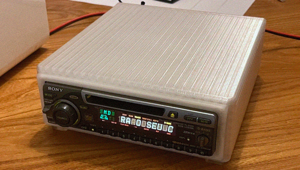
Car Stereo Hifi-Box Version 3
This is the v3 design. v1 never made it out of FreeCAD. v2 utilised an internal switching power supply which made it taller, in addition to a lidded design that meant the top was printed separately. That was a bad design choice only noticed when I realised that my panel cuts were too small and the entire thing would need to be re-printed.
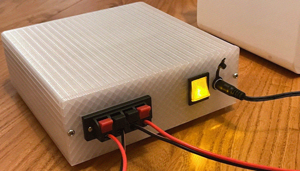
v3 doesn't use an internal PSU - it instead uses a 12VDC 10A power brick. Variation in voltage isn't a huge concern. Since this is a a car stereo it'll put up with a 10% swing either-way.The case is 3D printed PETG, and is printed in three parts - frame, back-panel, and a bazel. The back-panel went through a few re-designs, but nothing major beyond the thickness and arrangement. The bezel was a lot of trial-and-error, and the resulting model doesn't match the original exactly. But it gets close enough to do the job.
At this point, everything works. It's a finished project. But no project is ever really finished.
Caveats
So, here's what I'd probably fix/do if I wanted to keep going with this:
- Make the frame a bit deeper. It works as-is, but fitting in RCA panel mounts might be a bit much.
- Tweak the back holes for the brass inserts. For a better fit.
- Make the walls thinner to bring the PETG-use down (cur. ~400g).
- Expose the RCA input/output jacks. There's actually (hidden) cutouts for two RCA panel mounts.
Sources and BOM
Here's the files, you'll need FreeCAD to open them:
- The outer frame, which should be printed on-end
- The back panel, with optional (untested) RCA mounts
- A bezel
The parts you'll need are as follows:
| Part | Source | Notes |
|---|---|---|
| Sony 1DIN Minidisc Player | Ebay, Facebook Marketplace, etc | Ideally with cage and loom/harness |
| A 1DIN Cage | They're universal - just buy one that's 1DIN. | e.g. ASIN B004V88ZNG |
| A compatible loom/harness | Ebay, Halfords, etc | Optional, you can use spade connectors - we only use 3 pins. |
| A 12v >=10A DC Brick | Amazon, Farnell, Mouser, RS | A cheap one works. But I sleep more soundly using a Tiger TP1020. |
| Snap-in 12v >= 10A DC Switch | Amazon, Farnell, Mouser, RS | 29x21mm mounting diameter - I used ASIN B0BXKZK762. |
| >= 10A DC Barrel Panel Mount | Amazon, Farnell, Mouser, RS | 10.8mm mounting diameter - I used ASIN B0CH7WX85X. |
| 4-way Speaker Terminals | Amazon, Farnell, Mouser, RS | 60mm spacing. 70x24mm to fit recess - ASIN B07QR6228S. |
| 6mm OD M4 Knurled Insert Nuts <=5mm deep | All over the place | Fits flush, but epoxy wouldn't hurt. |
| M4 Screws | All over the place | I used 8mm long screws, but the case will probably handle up to 10mm. |
| 2.8, 4.8 and 6.3mm Spade Connectors | All over the place | 2.8 speakers, 4.8 fits loom, and 6.3 fits the switch. |
| Splicing Connectors | All over the place | I prefer WAGO Lever Nuts (Parts 221-412 and 221-413). |
Wiring Notes / Hacks
You should reference the service manual for your stereo, but the general pattern seems to be as follows. There are other wires, of course, such as the four for the rear speakers, one for the antenna, and another for telephony (or something). This project doesn't use them.
| Wire Colour | Purpose | Notes |
|---|---|---|
| Red | +12v Active Power | Normally tied to the car running, wire behind switch. |
| Yellow | +12v Passive Power (normally always live) | For the clock mostly. I wired it behind the switch. |
| Black | -12v | |
| White | Positive Left Speaker | |
| White and Black | Negative Left Speaker | |
| Grey | Positive Right Speaker | |
| Grey and Black | Negative Right Speaker |
In the case of the yellow wire, which is supposed to be +12v passive, you could certainly wire this in front of the switch so it is always live (which is how it would be in a car). This will avoid the clock always being 1AM when the stereo is turned on. I didn't do this because it felt like a good way to wear down the already old display.
You can certainly modify the case to reposition the speaker terminals and add a second set if you want rear-speakers. While I thought that would be pretty cool, I don't have four identical speakers that are low-power enough to get away with it.
The telephony stuff could maybe be abused to lower the volume on an arbitrary event. I haven't looked into it, but if the intent is to lower volume when a call occurs, I doubt it would be terribly difficult to wire up a wifi-capable microcontroller that can be used as an API. You already have stable DC power to work from.
Speaking of hacks - these Sony units have (1) RCA input, and (2) a proprietary remote that hasn't been considered in the case design. Modify the case to fit a Pi Zero with RCA out, figure out the remote protocol, and you could feasibly turn your car-stereo-box-thing into a streaming hifi.